 ar
ar bg
bg hr
hr cs
cs da
da nl
nl fi
fi fr
fr de
de el
el hi
hi it
it ko
ko no
no pl
pl pt
pt ro
ro ru
ru es
es sv
sv tl
tl iw
iw id
id lv
lv lt
lt sr
sr sk
sk sl
sl uk
uk vi
vi et
et hu
hu th
th tr
tr fa
fa ms
ms hy
hy ka
ka ur
ur bn
bn mn
mn ta
ta kk
kk uz
uz ku
ku
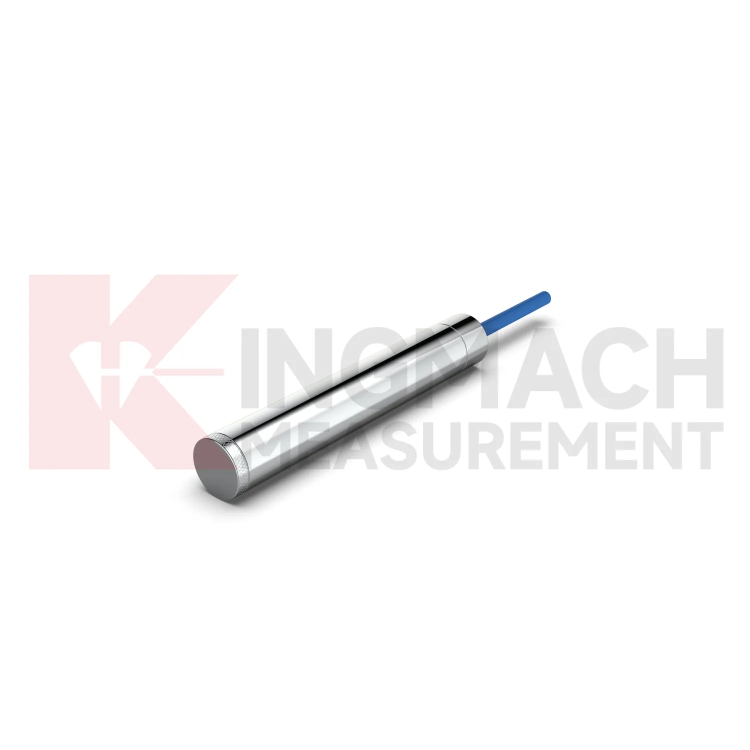
load cell wire diagram
Kingmach load cell wire diagram can also include pressure related sensing where soil or structural contact pressure is the main concern. The JMZX-50XXAT/ATM earth pressure cell family is listed in 0.3 MPa, 0.6 MPa, 1 MPa, 2 MPa, 4 MPa, 6 MPa, and 8 MPa ranges, with 0.001 MPa pressure resolution, 0.5%FS pressure accuracy, and ±0.5°C temperature accuracy. The product information also refers to high strength elastic steel, waterproof and durable construction, a 50 year design life, 800 stored measurement sets, and automated acquisition support. For retaining structures, embankments, dams, tunnels, and foundation pits, those pressure records help engineers understand whether earth load, water influence, compaction, or excavation stage changes are affecting the structure. Kingmach's broader monitoring catalog allows these readings to be compared with settlement, water pressure, displacement, and tilt. That connection is important because pressure change without movement may still indicate a developing load redistribution that deserves closer inspection. The same site places these instruments within a wider monitoring range, including piezometers, water level meters, displacement transducers, settlement sensors, tiltmeters, cables, data loggers, and software. That wider range helps when a project needs force data to be compared with movement, water, and temperature records.
Application of load cell wire diagram
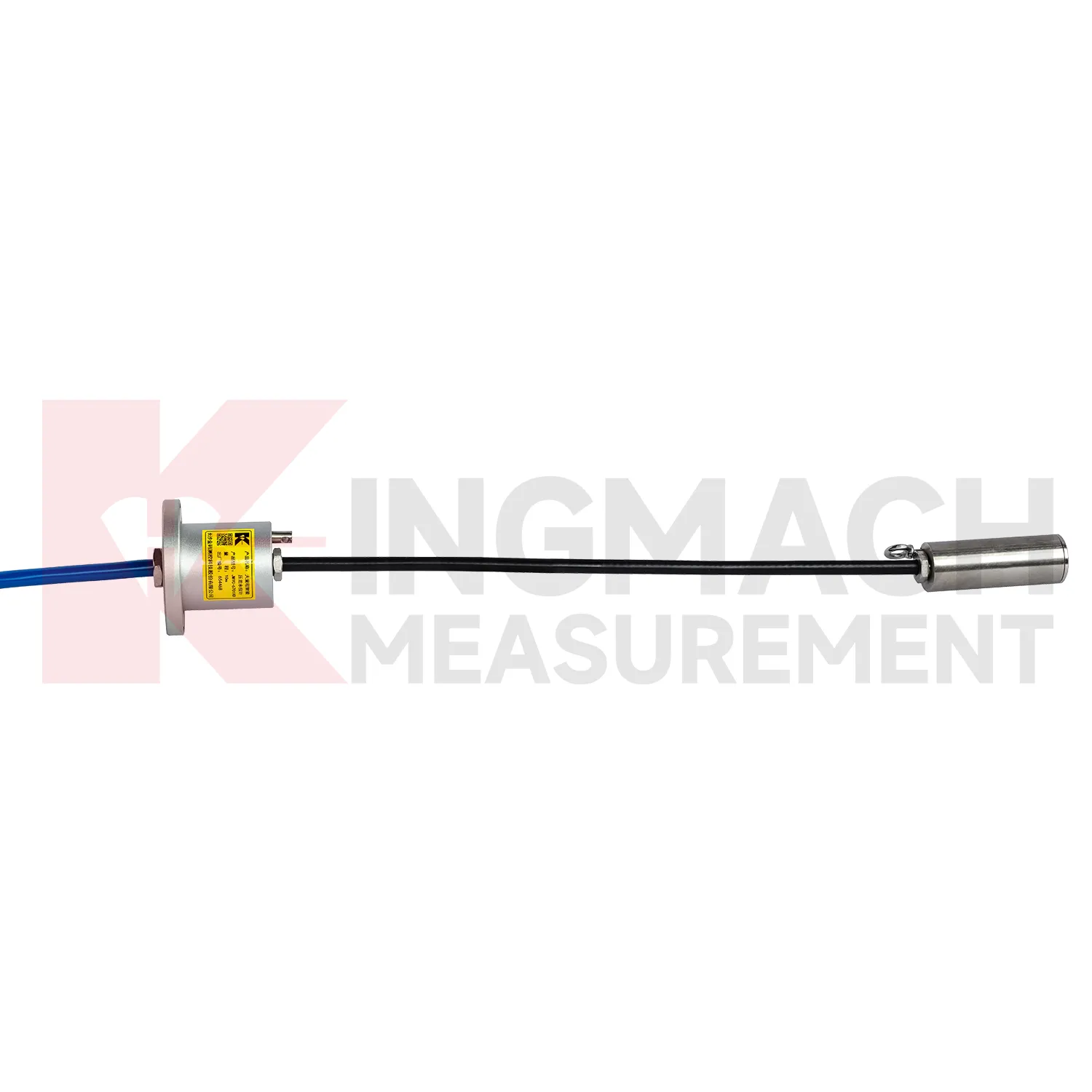
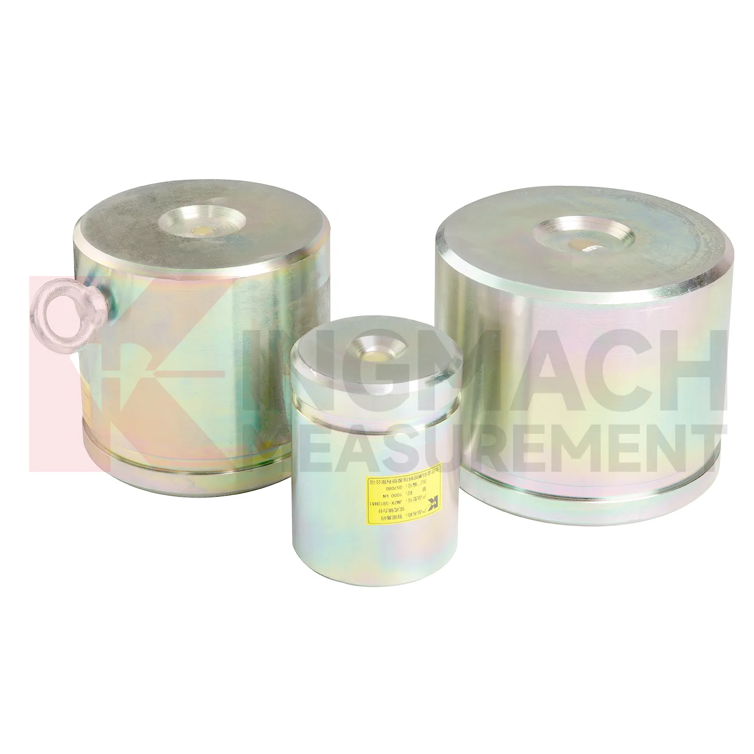
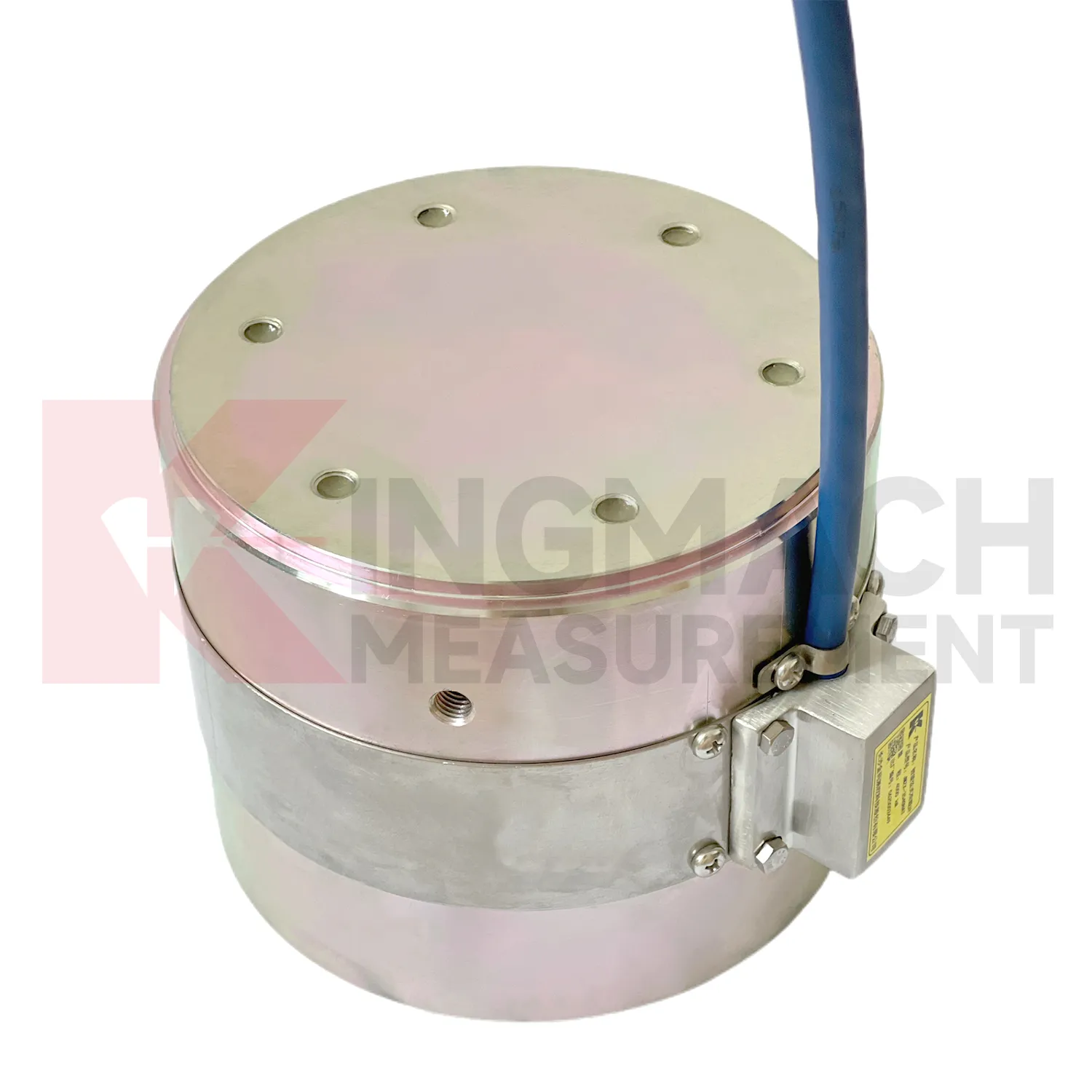
In tunnel engineering and underground works, load cell wire diagram is often placed on steel supports, temporary struts, surrounding rock pressure points, or contact zones near retaining elements. The main monitoring need is early detection of force change during excavation, lining work, grouting, groundwater fluctuation, or nearby construction. The JMZX-38XXHAT axial force load meter lists 200 kN to 3000 kN ranges, 0.1 kN or 1 kN sensitivity, 0.5%FS accuracy, direct kN display, and a 1 MPa waterproof rating. These parameters suit wet, crowded, and time sensitive underground sites. Where soil or contact pressure is the issue, earth pressure cells with 0.3 MPa to 8 MPa ranges and 0.001 MPa resolution can be added. The field problem is usually not a lack of readings, but knowing which reading belongs to which stage. Clear channel names, protected cables, and first stable readings after each excavation step help teams see whether the support system is loading normally or moving toward a risky pattern. For underground work, the first stable reading after each support stage should be kept with excavation depth, support time, and groundwater condition. That extra context helps explain whether a force change belongs to the structure, the soil, or the construction sequence.
The future of load cell wire diagram
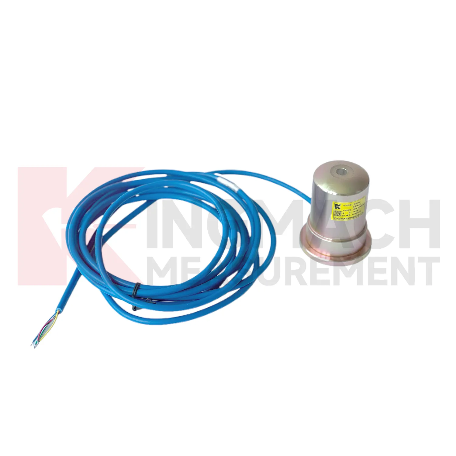
Future load cell wire diagram use will depend on cleaner data pipelines, not only stronger metal parts. Kingmach's smart load cell features, including digital output, long distance transmission, anti-interference performance, temperature correction, and stored parameters, already point toward connected monitoring. In the next few years, more projects are likely to use edge acquisition units that check whether a reading is plausible before it reaches the platform. A sudden force jump can be compared with temperature, cable condition, nearby displacement, and recent construction events. AI based warning tools may help sort routine fluctuation from patterns that deserve inspection, but they will only work when the instrument record is consistent. That places more value on channel naming, calibration certificates, zero checks, installation photos, and maintenance logs. The product direction is therefore practical: robust sensing at the point of load, reliable transmission from difficult sites, and software that helps engineers review trends without losing the original measurement context.
Care & Maintenance of load cell wire diagram
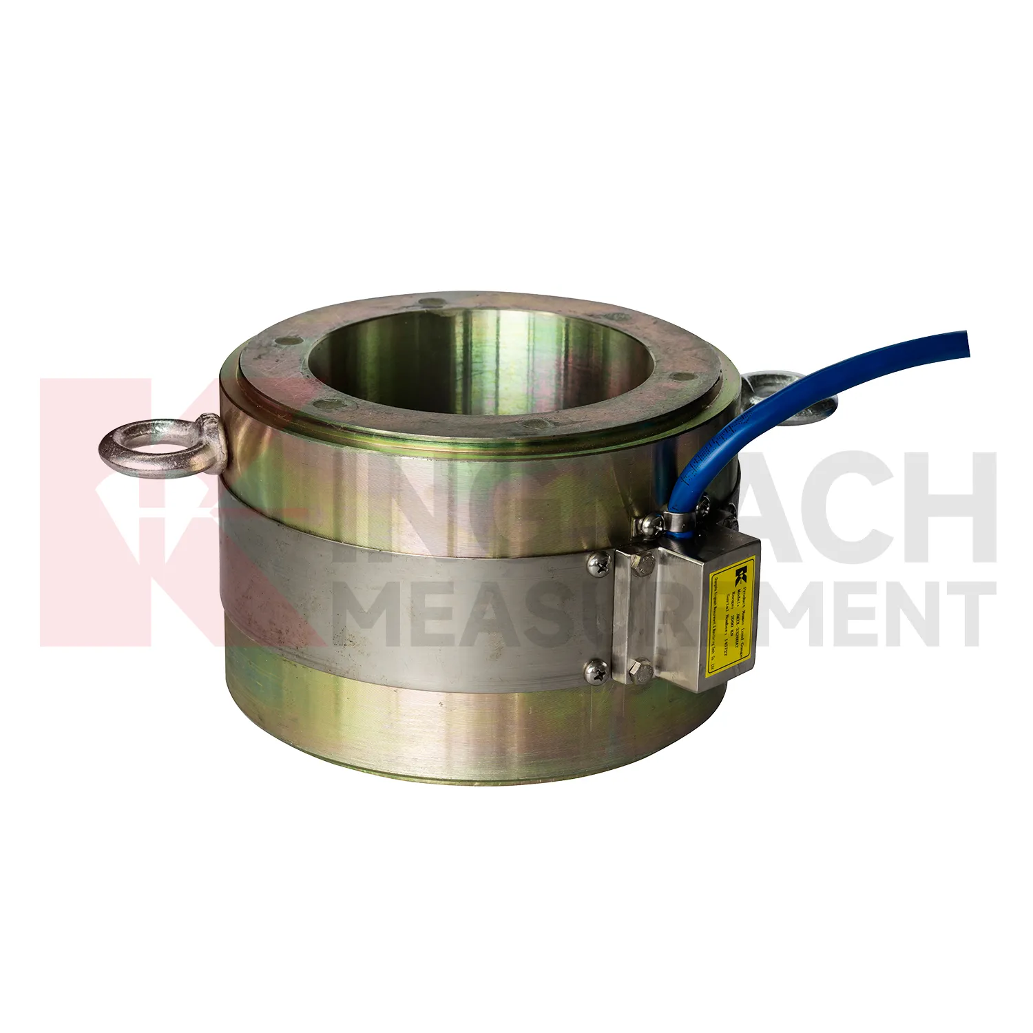
For load cell wire diagram used in pile load testing, care begins before the first load step. Confirm that the selected solid load cell range, often between 1000 kN and 10000 kN on Kingmach listed models, exceeds the planned test load with proper margin. Check the 0.1 kN resolution, 0.5%FS precision, calibration certificate, bearing plate flatness, and centering arrangement. During the test, protect the cable from jack movement and keep the readout position safe from vibration and water. Record zero value, temperature, load stage, hold time, unloading stage, and any pause or adjustment. After the test, inspect the sensor for dents, side load marks, connector damage, and cable jacket cuts. Store the calibration coefficient with the test report, not only with the instrument box. If later readings appear inconsistent, compare them with jack pressure, settlement data, and loading procedure before blaming the sensor. Store the report with the test file.
Kingmach load cell wire diagram
load cell wire diagram belongs at the point where a drawing stops being a guess and the structure begins to report what is really happening. In Kingmach engineering monitoring, force data is used around bridge cables, anchor heads, pier bearings, pile tests, retaining systems, and temporary steel supports. The reading is not only a number in kN. It is a record of where the force sits, when it changed, and which construction or service condition caused that change. A practical monitoring plan often pairs force with displacement, settlement, tilt, temperature, water pressure, or rainfall, because load rarely moves alone. For procurement teams, the useful questions are direct: capacity range, accuracy, installation space, cable route, waterproofing, calibration record, and data acquisition method. When these items are settled before site work starts, the same instrument can support acceptance checks, construction control, and later maintenance decisions without forcing engineers to rebuild the data story. That early planning also keeps later reports from mixing force trends with installation doubts.
FAQ
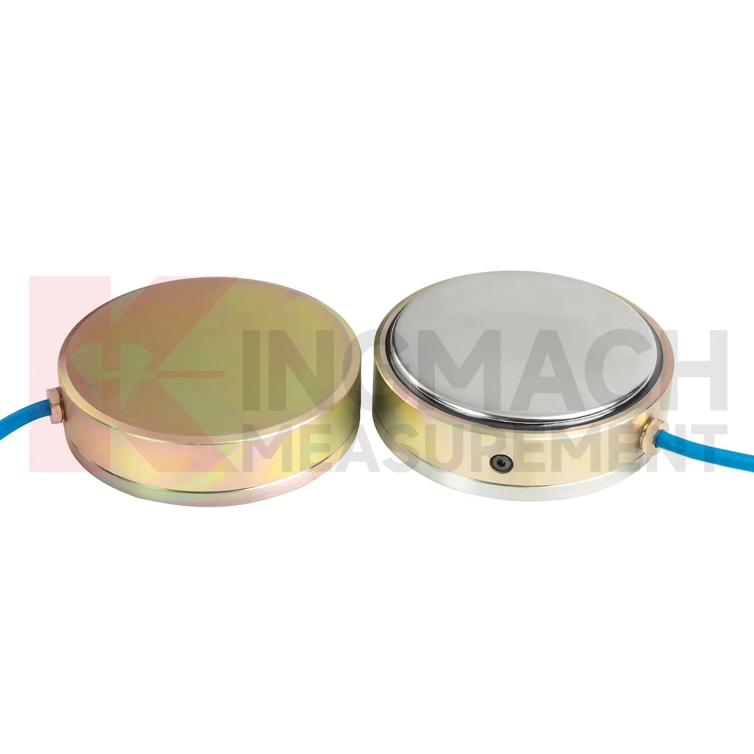
Q: How should load cell wire diagram be selected for a bridge cable or anchor point? A: Start with expected force, lock-off load, possible overload, bearing geometry, and access for later inspection. Hollow load cells are commonly used where the anchor or cable passes through the center opening. Q: What range information is available from Kingmach hollow models? A: The JMZX-3XXXHAT series is listed from 500 kN to 8000 kN, with 0.1 kN sensitivity on the 500 kN model and 1 kN on larger listed models. Q: Why does temperature correction matter? A: Cable and anchor readings can move with temperature, so built-in temperature measurement helps reduce false interpretation. Q: Can readings be stored inside the sensor? A: Smart hollow models list storage for 800 measurement records, including time, temperature, zero values, and correction data. Q: What should be checked after installation? A: Check seating, cable protection, connector sealing, zero value, first stable force, and matching channel name.
Reviews
Michael Anderson
The strain gauges and load cells are extremely accurate and stable. They performed very well in our bridge monitoring project. Highly recommended!
Daniel Brown
Excellent environmental monitoring sensors. The data is consistent, and the system integrates smoothly with our existing setup.
Latest Inquiries
To protect the privacy of our buyers, only public service email domains like Gmail, Yahoo, and MSN will be displayed. Additionally, only a limited portion of the inquiry content will be shown.
Isabella***@gmail.comGermany
Hello, we are evaluating weir flow meters for a water management project. Please share accuracy deta...
Ava***@gmail.comAustralia
Hi, I am looking for reliable tiltmeters and accelerometers for structural health monitoring. Please...