
 EN
EN
 ar
ar bg
bg hr
hr cs
cs da
da nl
nl fi
fi fr
fr de
de el
el hi
hi it
it ko
ko no
no pl
pl pt
pt ro
ro ru
ru es
es sv
sv tl
tl iw
iw id
id lv
lv lt
lt sr
sr sk
sk sl
sl uk
uk vi
vi et
et hu
hu th
th tr
tr fa
fa ms
ms hy
hy ka
ka ur
ur bn
bn mn
mn ta
ta kk
kk uz
uz ku
ku
Real-Time Dam Safety Alerts with Differential Pressure Water Level Sensors
Key Takeaways An alert chain needs more than a sensor: define field in...

Load Cell Wiring Schematic: Avoid the Common Pitfalls
A wiring mistake is easy to make—and the effect on readings can be subtle. A poorly routed cable, a floating shield, or mixing up sense and excitation leads in a 6-wire configuration can turn a precision load cell into a noise source. Over time, those millivolt-level errors add up, especially in geotechnical or structural monitoring where long-term stability matters. This page breaks down the basics of load cell wiring schematics, focusing on what gets missed in typical datasheets. We’ll look at 4-wire and 6-wire setups, how to handle cable shielding, and why color codes can vary between manufacturers. Kingmach produces a range of load cells and monitoring instruments, and we often see the same wiring questions come up from our customers. The information here reflects that field experience—not just textbook theory.
Technical Detail
Most load cells use a Wheatstone bridge circuit, which means you’re dealing with four active wires: excitation + and –, and signal + and –. A basic 4-wire schematic is straightforward, but voltage drops along long cables can affect accuracy. That’s where a 6-wire setup helps: the extra pair of sense lines lets the measuring device compensate for cable resistance. In practice, though, getting that compensation to work reliably comes down to clean connections and correct grounding. Shielding is another area where schematic drawings often oversimplify. The drawing might show the shield connected to ground at one end, but in the field, you’ll encounter ground loops if both the instrument and the junction box are earth-grounded differently. With load cells installed outdoors—think pile testing or dam monitoring—moisture and temperature swings test every connection. Kingmach manufactures load cells and related geotechnical instruments. While we don’t sell generic wiring kits, our technical team regularly helps customers interpret their wiring schematics. We’ve seen that many issues boil down to color code mismatches. Different manufacturers use different wire colors: one’s red excitation + might be another’s green. Our documentation includes clear pinouts for all standard configurations, and we can customize cabling for specific project requirements. Whether you’re connecting to a handheld readout or a permanent data logger, the same rules apply: keep excitation stable, route signal wires away from AC power, and double-check the sense line connections. A few minutes spent verifying against the schematic can prevent weeks of chasing intermittent data problems.
News
Key Takeaways An alert chain needs more than a sensor: define field in...
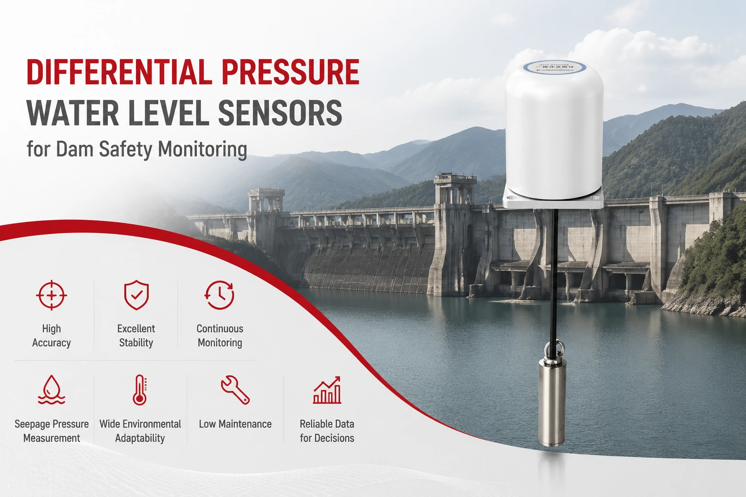
Key Takeaways The strongest fit is usually a confined, submerged, or s...
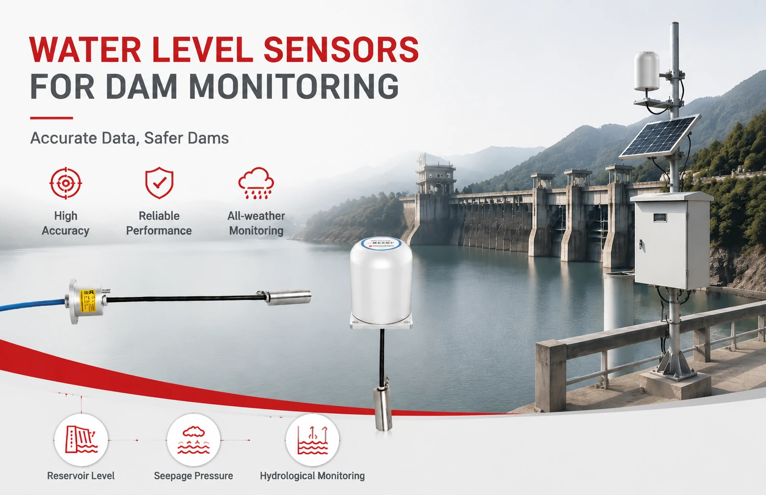
Kingmach Water Level Sensors for Dam Monitoring: A Buyer's Guide to Differential Pre...
Products
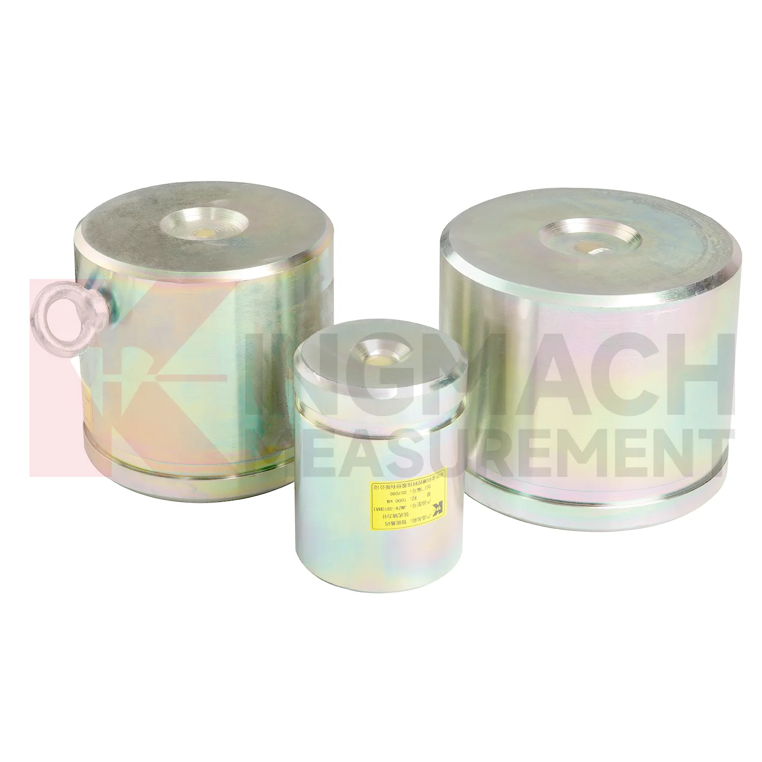
Axial Force Load Meter ( VW & Smart Type)JMZX-38XXHAT
View Details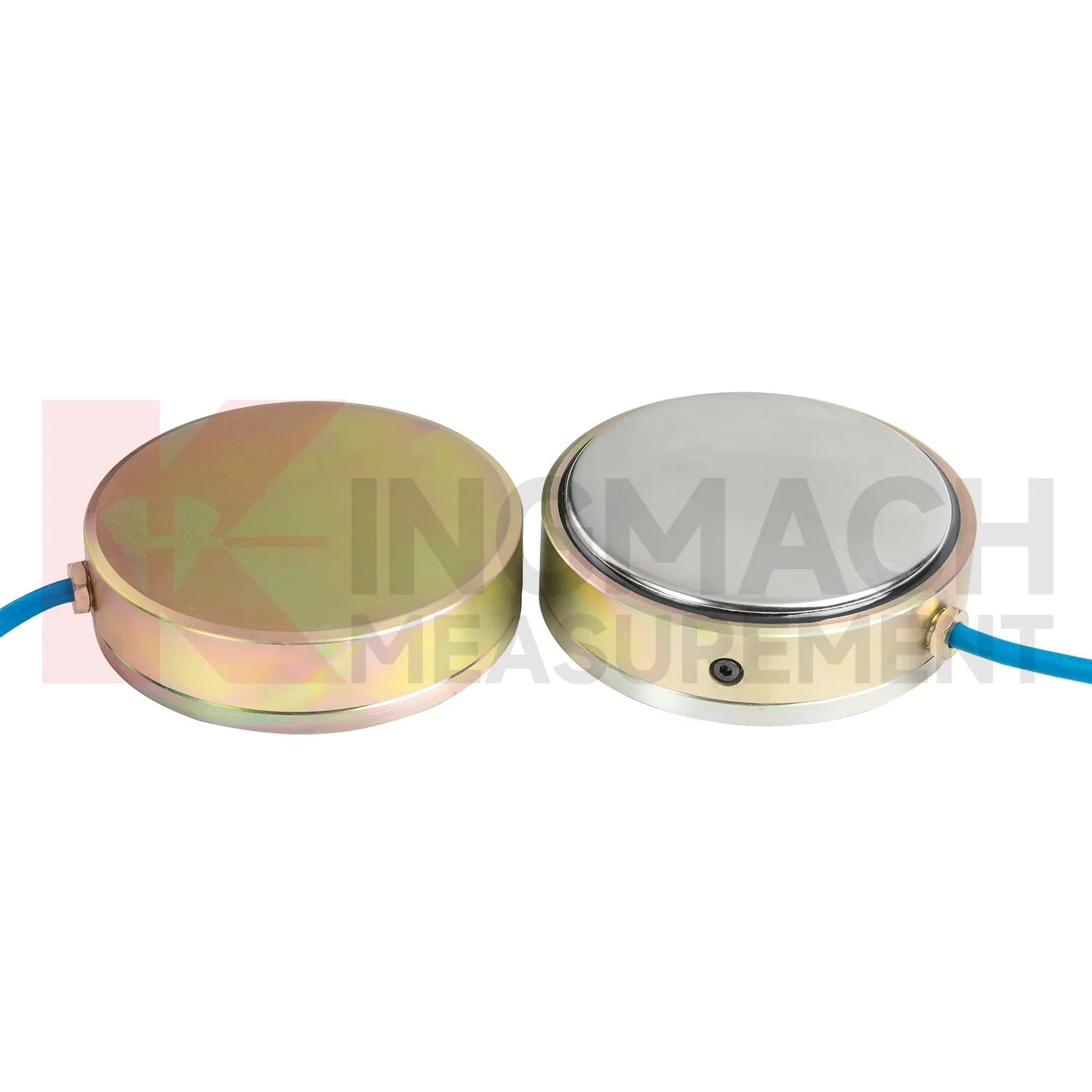
Large Earth Pressure Cell ( VW & Smart Type) JMZX-51XXAT/ ATM
View Details
Smart Vibrating Wire PiezometerSmart Piezometers (VW) JMZX-55XXHAT
View DetailsFAQ
A 4-wire load cell has two excitation wires and two signal wires. With long cable runs, the cable resistance adds to the excitation circuit, causing a small voltage drop which throws off the calibration. A 6-wire load cell adds a pair of sense wires that monitor the voltage right at the load cell. The measuring instrument can then adjust the excitation to compensate. For cables longer than about 10 meters, 6-wire is the safer choice—it’s what most of our geotechnical monitoring systems use.
Yes, drifting readings often point to a wiring or moisture issue. A common culprit is a shield that’s connected at both ends, creating a ground loop. Also check for loose terminals, especially in junction boxes subject to vibration. Over time, water ingress into the cable can lower insulation resistance between wires, leading to slow drift. If you’re using a 6-wire cell, make sure the sense lines are firmly joined to the excitation lines near the load cell—otherwise the compensation circuit can become unstable.
Wire color codes are not standardized across all brands. Always refer to the datasheet that came with your specific load cell. Kingmach provides a calibration sheet with each instrument that includes the exact color scheme and pinout. If you’ve lost the sheet, contact our support with the model number—we keep records. As a general rule, red and black often represent excitation + and –, while green and white are signal + and –, but do not assume this without verification.
Best practice is to ground the shield at the instrument end only—that is, at the readout, logger, or amplifier. Connecting the shield at the load cell end can create a path for ground currents, especially if the load cell body is already electrically in contact with the structure. In some situations, leaving the shield completely disconnected at the load cell and just ensuring the load cell housing is locally grounded works well. Our wiring diagrams clearly show the recommended shield landing point for each product series.
Share your product type, target capacity, and application requirements. Our team can review the details and recommend a practical next step.
If you are interested in our products or want to become our partner.
Please leave your contact information, our team will contact you as soon as possible.
Mail: [email protected]
Contact Us: +8613808434127
Address: No. 188 Tongzipo West Rd, Changsha, Hunan, China